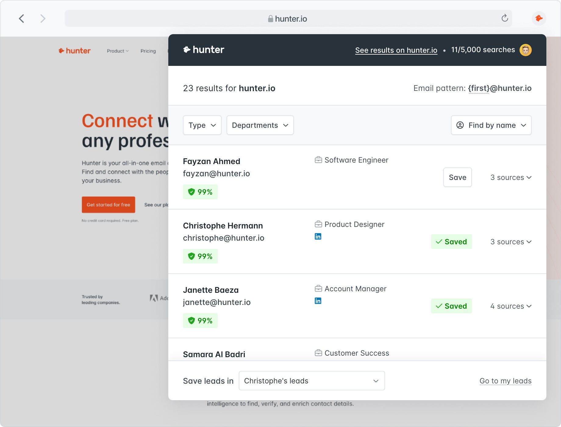
Find who to contact when you visit a website.

Find email addresses while you're browsing the web.
Add to Firefox — it's free
It's magic. I go to a website and can immediately get email addresses — complete with a confidence score so I can gauge how accurate the info is. This has saved me hours and loads of frustration. Highly recommend.Patricia Browne Lead Generation Specialist
Install Hunter’s Firefox extension and find the email addresses behind the websites you're browsing.
Add to Firefox — it's freeThe Autodesk Subassembly Composer (SAC) is a powerful tool designed to help civil engineers and designers create custom corridor components without the need for complex .NET programming. While many users look for a tutorial PDF to master its logic, the core of SAC lies in its visual flowchart-based interface, which bridges the gap between standard out-of-the-box subassemblies and highly specialized project requirements. The Role of Custom Subassemblies in Design
In Civil 3D, a subassembly is a drawing object that defines the geometry for corridor sections, such as lanes, curbs, or ditches. While Civil 3D provides a vast library of stock components, unique engineering challenges—like complex grading or specific structural details—often require custom solutions. The Subassembly Composer allows users to build these "smart" objects that react dynamically to targets like surfaces, offsets, and elevations. Key Components of Subassembly Logic
To master SAC, a designer must understand three fundamental building blocks:
Points, Links, and Shapes: Points define the location of vertices; Links connect points to form edges; and Shapes are closed loops used for material quantity takeoffs.
Input/Output Parameters: These are the "knobs" that users turn in Civil 3D (e.g., width, slope, or thickness) to adjust the subassembly behavior without reopening the composer.
Coding: Assigning Point, Link, and Shape codes is critical. These codes allow Civil 3D to automatically generate feature lines, apply labels, and render materials in the final corridor model. Workflow: From Composer to Corridor
The process of implementing a custom subassembly typically follows a four-step lifecycle:
Creation: Building the geometry and logic flowchart within the Subassembly Composer interface.
Saving: Files are saved as .pkt (packet) files, which contain all the geometry and metadata.
Importing: Users must import the .pkt file into a Civil 3D Tool Palette to make it accessible for use in an assembly.
Deployment: Once imported, the subassembly is added to an assembly object to form a complete road or channel cross-section. Common Challenges
Even with a solid tutorial, designers often face issues such as version mismatches between the SAC version and the Civil 3D version, which can cause graphics to disappear or fail to update. Regular maintenance and ensuring that all project collaborators use the same subassembly definitions are essential for corridor stability.
By utilizing resources like the official Autodesk Help documentation or comprehensive guides from FDOT (Florida Department of Transportation), designers can move beyond standard templates to create truly bespoke infrastructure models. FDOT Civil 3D Subassembly Composer
For a deep dive into Civil 3D Subassembly Composer (SAC) , several authoritative PDF guides and "handouts" from Autodesk University and state DOTs provide comprehensive, step-by-step instructions. These tutorials cover everything from basic geometry to complex conditional logic. 📘 Essential Tutorial PDFs
The following resources are highly regarded for their structured approach to SAC: Subassembly Composer Beginner Lab Guide
: An ideal starting point that walks through creating a subassembly from scratch, including dragging and dropping flowchart elements and setting up input/output parameters. FDOT Subassembly Composer Course Guide
: A detailed professional workflow from the Florida Department of Transportation, breaking down the process into six clear steps: project creation, parameter specification, geometry addition/modification, previewing, and importing into Civil 3D. Compose Like Beethoven: Simple to Complex
: A tutorial focused on building a box culvert, teaching users how to define packet settings and handle more advanced shape requirements. Advanced Lessons in SAC
: Covers "deep features" such as surface targets, which allow subassemblies to dynamically adjust to existing ground conditions. 🛠️ Key Concepts Covered in These Guides
These manuals typically focus on the five main areas of the SAC interface: Subassembly Composer, Simple to Complex | Autodesk
Basic Box Culvert Subassembly. In this exercise, you will create a simple box culvert using the following steps: 1. Launch SAC. a. FDOT Civil 3D Subassembly Composer
Autodesk Subassembly Composer (SAC) is a powerful companion application for Civil 3D that allows users to build complex, custom subassemblies through a visual, logic-based interface without traditional programming. Key Interface Components
The SAC environment is composed of five primary windows that facilitate the design process:
Toolbox: Contains the building blocks, such as geometry (points, links, shapes), advanced logic (decisions, switches), and auxiliary components.
Flowchart: The central workspace where you drag and drop components from the toolbox to define the calculation sequence.
Preview: Provides a real-time visual representation of the subassembly in either "Layout Mode" (how it appears on an assembly) or "Roadway Mode" (how it reacts to targets).
Properties: Used to define the specific numerical values, math expressions, or variable names for the selected element in the flowchart.
Settings & Parameters: Includes tabs for Packet Settings (naming and help files), Input/Output Parameters (user-defined variables), and Target Parameters (surface, offset, or elevation targets). Core Workflow for Creating a Subassembly
A typical design workflow follows these six foundational steps: Subassembly Composer Pt. 1 - Exploring the Interface
Introduction
Autodesk Civil 3D is a powerful software tool used for civil engineering design and construction. One of its key features is the Subassembly Composer, which allows users to create custom subassemblies for use in corridor design. In this paper, we will provide an overview of the Civil 3D Subassembly Composer and offer a step-by-step tutorial on how to use it.
What is a Subassembly?
In Civil 3D, a subassembly is a reusable component that can be used to build a corridor. It is a collection of one or more feature lines, surfaces, and other components that work together to create a specific design element, such as a curb and gutter or a sidewalk. Subassemblies can be used to create complex designs, such as intersections, interchanges, and roundabouts.
What is the Subassembly Composer?
The Subassembly Composer is a tool within Civil 3D that allows users to create custom subassemblies. It provides a graphical interface for designing and testing subassemblies, making it easier to create complex designs. With the Subassembly Composer, users can:
Tutorial: Creating a Simple Subassembly with the Subassembly Composer
In this tutorial, we will create a simple subassembly for a curb and gutter.
Step 1: Launch the Subassembly Composer
Step 2: Create a New Subassembly
Step 3: Define the Subassembly Parameters civil 3d subassembly composer tutorial pdf
Step 4: Create the Subassembly Components
Step 5: Add a Gutter Component
Step 6: Connect the Components
Step 7: Test the Subassembly
Step 8: Save the Subassembly
Conclusion
In this tutorial, we created a simple subassembly for a curb and gutter using the Civil 3D Subassembly Composer. The Subassembly Composer is a powerful tool that allows users to create custom subassemblies for use in corridor design. By following these steps, users can create complex designs and improve their productivity.
Additional Resources
For more information on the Civil 3D Subassembly Composer, please refer to the following resources:
PDF Resources
Here are some PDF resources that you can download to learn more about the Civil 3D Subassembly Composer:
Autodesk University publishes class handouts that are often more practical than the official manual.
Autodesk Subassembly Composer (SAC) is a visual programming tool included with Autodesk Civil 3D
that allows users to create complex, custom subassembly parts for corridor models without needing to write code. Core Interface Panels
The SAC interface consists of five primary panels designed to help you build and verify your designs visually: : Contains the building blocks like
, as well as advanced geometry and workflow logic (e.g., Decisions).
: The central workspace where you drag and drop nodes from the Toolbox to define the assembly's logic and sequence.
: A real-time visual representation of your subassembly, allowing you to test how it reacts to different parameters and targets. Properties
: Used to define specific coordinates, codes, and logic for any item selected in the Flowchart. Packet Settings & Parameters : Where you name the subassembly and define Input/Output parameters Target parameters (like surfaces or offsets), and Superelevation Typical Design Workflow
Creating a custom subassembly generally follows these six steps: fdotwww.blob.core.windows.net Initialize Project
: Start a new project and set the subassembly name in the Packet Settings. Define Parameters
: Create Input parameters (e.g., width, depth) and Target parameters (e.g., surface, offset) that users can adjust later in Civil 3D. Add Geometry
: Drag and drop Points, Links, and Shapes into the Flowchart. Apply Logic
node to create conditional geometry, such as different slopes for "Cut" vs "Fill" scenarios. Test in Preview
: Adjust the values in the Preview panel to ensure the geometry behaves as expected. Export & Import : Save the file as a
and import it into a Civil 3D Tool Palette for use in corridor design. Key Learning Resources (PDF Guides)
For deep-dive tutorials, you can refer to these authoritative white papers and handouts:
Civil 3D Subassembly Composer Tutorial: A Step-by-Step Guide
Introduction
Autodesk Civil 3D is a powerful software used for civil engineering design and construction. One of its key features is the Subassembly Composer, a tool that allows users to create custom subassemblies for use in corridor design. In this tutorial, we will guide you through the process of creating a simple subassembly using the Subassembly Composer.
What is a Subassembly?
In Civil 3D, a subassembly is a collection of components that work together to form a part of a corridor. Subassemblies can be thought of as building blocks that can be used to create complex corridor designs. They can be used to represent a variety of features, such as lanes, shoulders, medians, and sidewalks.
What is the Subassembly Composer?
The Subassembly Composer is a tool within Civil 3D that allows users to create custom subassemblies. It provides a graphical interface for defining the components of a subassembly and how they interact with each other. With the Subassembly Composer, users can create complex subassemblies without having to write code.
Step 1: Launching the Subassembly Composer
To launch the Subassembly Composer, follow these steps:
Step 2: Creating a New Subassembly
Once the Subassembly Composer is launched, follow these steps to create a new subassembly:
Step 3: Adding Components
Components are the building blocks of a subassembly. They can represent features such as points, lines, and curves. To add a component to your subassembly, follow these steps:
Step 4: Defining Component Properties
Once you have added a component, you need to define its properties. Properties can include things like the component's location, slope, and elevation. To define component properties, follow these steps:
Step 5: Creating Relationships Between Components
Relationships between components define how they interact with each other. To create a relationship between components, follow these steps:
Step 6: Testing and Saving the Subassembly
Once you have defined your subassembly, you can test it to make sure it works as expected. To test the subassembly, follow these steps:
Step 7: Saving the Subassembly
Once you are satisfied with your subassembly, you can save it for use in corridor design. To save the subassembly, follow these steps:
Conclusion
In this tutorial, we have guided you through the process of creating a simple subassembly using the Subassembly Composer. With practice, you can create complex subassemblies to represent a wide range of corridor features.
Additional Resources
For more information on the Subassembly Composer, we recommend the following resources:
Downloadable PDF Tutorial
A downloadable PDF tutorial on Civil 3D Subassembly Composer is available from Autodesk website. The tutorial provides a step-by-step guide on creating a subassembly, including screenshots and detailed instructions.
Tips and Tricks
Here are some tips and tricks to keep in mind when using the Subassembly Composer:
By following these steps and practicing with the Subassembly Composer, you can become proficient in creating custom subassemblies for use in corridor design.
Finding high-quality Civil 3D Subassembly Composer (SAC) tutorials often means digging through Autodesk University (AU)
handouts. These "papers" are typically expert-led guides that include step-by-step instructions, logic explanations, and "cheat sheets" for expressions. Highly Recommended "Useful Papers" (PDFs) Analyze and Devise in Subassembly Composer
by Kati Mercier: Widely considered the "gold standard" tutorial. It covers everything from basic geometry to complex fill-over-surface logic and includes a valuable API expression reference. Subassembly Composer: Simple to Complex
: A comprehensive class handout that starts with UI basics and moves into modeling corridors and troubleshooting custom PKT files FDOT Civil 3D Subassembly Composer Course Guide
: A very structured, practical guide from the Florida Department of Transportation. It is excellent for learning how to set up fixed geometry, targets, and input/output parameters. Reverse Engineering with Subassembly Composer
: This paper is best for users who want to understand the underlying VB Expressions and logic needed for advanced "thinking" subassemblies. Autodesk Community, Autodesk Forums, Autodesk Forum Quick Start Checklist
If you are just opening the software, these are the core components you'll need to master as outlined in these papers: Subassembly composer - Forums, Autodesk
To get the "full story" on mastering the Civil 3D Subassembly Composer (SAC)
, you need to understand that it is a standalone visual programming tool used to create custom roadway, rail, or grading components (PKT files) that aren't available in the standard Civil 3D library. FDOT (.gov) Core Workflow of Subassembly Composer
The tool operates on a logic-based flowchart system rather than traditional CAD drawing: Define Input Parameters
: Set variables like width, slope, or material depth that you can later change inside Civil 3D. Build the Flowchart Geometry Elements (Points, Links, and Shapes) to define the cross-section. Apply Logic
nodes (if/then statements) to make the subassembly adapt to different conditions, such as "if in cut, use a ditch; if in fill, use a simple daylight slope." Surface, Offset, or Elevation Targets
so the subassembly can stretch or snap to existing site conditions in your corridor. Eagle Point Software Essential Tutorial Resources (PDF & Documentation)
While many physical "PDF" manuals are now integrated into online help systems, these are the primary official and expert guides: Official Autodesk SAC Documentation
: This is the definitive "User Guide" which covers the interface, API functions, and logic workflows. Civil 3D SAC Learning Path (Eagle Point)
: A structured approach to learning the 2026 and earlier versions, focusing on complex grading challenges. FDOT C3D Documentation
: State DOTs often provide detailed, downloadable PDFs and manuals for specific subassembly standards. FDOT (.gov) How to Use Your Custom Subassembly Once you have designed your logic in the Composer: Save as .PKT : This is the file format for custom subassemblies. Import to Civil 3D : Open your Tool Palette in Civil 3D, right-click, and select Import Subassemblies to bring in your .pkt file. Build the Assembly
: Place your custom part onto an assembly marker to use it in a step-by-step example of creating a "Decision" node for a cut/fill ditch? FDOT C3D SubAssembly Composer
Civil 3D Subassembly Composer Quick-Start Guide The Autodesk Subassembly Composer (SAC) allows you to build custom roadway components without complex programming. Follow these steps to create, define, and import your first custom subassembly. 1. Launch & Set Up
Open SAC: Launch the application from the Windows Start menu (typically found under the Autodesk folder).
Create Project: Start a new project and go to the Packet Settings tab. The Autodesk Subassembly Composer (SAC) is a powerful
Define Name: Enter a unique Subassembly Name (required). This name will identify the component when it is imported into Civil 3D.
Organize: Create a dedicated folder for your .pkt files to keep versions and support images organized. 2. Define Parameters
Before drawing, set the rules for how the subassembly behaves in Civil 3D.
Input/Output Parameters: Define variables the end-user can change, such as "Lane Width" or "Pavement Thickness".
Target Parameters: Set up horizontal and vertical targets (e.g., "Alignment" or "Surface") so the subassembly can dynamiclly stretch to meet project site conditions. 3. Build the Geometry Use the Toolbox to drag elements into the Flowchart window. AutoCAD Civil 3D and Subassembly Composer - Autodesk
Master Civil 3D Subassembly Composer: A Comprehensive Guide For infrastructure professionals, the standard subassemblies provided in Autodesk Civil 3D often fall short of complex, real-world design requirements. Whether you are dealing with variable sidewalk widths, complex retaining walls, or specific regional drainage standards, the Civil 3D Subassembly Composer (SAC) is your essential tool for custom corridor modeling.
This guide serves as a foundational tutorial for those looking to master SAC, providing a structured approach to building intelligent, adaptive subassemblies. What is Subassembly Composer?
The Subassembly Composer is a visual programming interface that allows users to create complex subassemblies (the building blocks of a "corridor assembly") without needing to write hard code. By using a flowchart-based logic, you can define how points, links, and shapes behave based on specific parameters and target surfaces. Key Benefits:
Customization: Create specific shapes not found in the out-of-the-box library.
Intelligence: Build "logic" into your parts (e.g., "if the fill height is > 5ft, use a specific slope").
Dynamic Updating: Subassemblies built in SAC react instantly to changes in your Civil 3D model. 1. Navigating the Interface
Before diving into the logic, you must understand the five primary windows in the SAC interface:
Toolbox: Contains the building blocks (Geometry, Advanced Geometry, and Auxiliary tools).
Flowchart: The "brain" where you drag and drop elements to create the logic sequence.
Preview: A real-time visual representation of your subassembly.
Properties: Where you define specific coordinates, names, and math for each point/link.
Input/Output Parameters: The tab where you define variables (like "Lane Width" or "Pave Depth") that users can change inside Civil 3D. 2. Setting Up Your Parameters
The biggest mistake beginners make is hard-coding numbers (like 12ft for a lane). Instead, always use Input Parameters.
Side: Use the "Side" parameter so the subassembly knows if it is on the Left or Right.
Width & Slope: Create Type "Double" parameters for these values.
Target Parameters: If your subassembly needs to find a Surface or an Alignment, define these here. 3. Building the Geometry (Points, Links, and Shapes)
The hierarchy of any subassembly is Points > Links > Shapes. Step 1: Points (P)
Every subassembly starts at the Origin (0,0). From there, you create P2, P3, etc. You can define points by: Delta X and Delta Y: Move a specific distance. Slope and Delta X: Move at a 2% slope for 12 feet. Step 2: Links (L)
Links connect your points. These represent the surfaces (Top, Datum) or the vertical edges of your curbs and layers. Step 3: Shapes (S)
Once you have a closed loop of links, you add a "Shape." This allows Civil 3D to calculate material volumes (e.g., concrete, subbase, or asphalt). 4. Advanced Logic: Using Decisions
The true power of SAC lies in the Decision node. This allows your corridor to "think." Example Scenario: Condition: OffsetTarget.IsValid
True: The subassembly stretches to meet a specific line in your drawing.
False: The subassembly uses a default fixed width of 12 feet. 5. Coding and Point/Link Codes
For your custom subassembly to work correctly in Civil 3D, you must assign Codes. Point Codes: "Pave", "Curb", "Hinge". Link Codes: "Top", "Datum", "Pave1".
Without these codes, Civil 3D won't be able to generate surfaces or render the corridor correctly in cross-sections. 6. Importing into Civil 3D Once your .pkt file is saved, importing it is simple: Open Civil 3D. Open your Tool Palette. Right-click on the palette and select Import Subassemblies.
Select your .pkt file. It is now ready to be added to an Assembly! Troubleshooting Common Errors
Looping Logic: Ensure your flowchart doesn't create an infinite loop.
Missing Shapes: If a shape doesn't appear in the preview, check that all links are properly connected.
Target Not Found: Always set a "Preview Value" for targets in SAC to ensure the logic works before moving to Civil 3D. Conclusion
Mastering the Subassembly Composer moves you from being a standard drafter to a high-level BIM designer. By moving away from static blocks and toward dynamic, logic-based subassemblies, you reduce manual rework and increase the accuracy of your infrastructure models.
Pro-Tip: Always document your SAC files internally. Because the logic can get complex, adding "Comments" within the flowchart will help your teammates understand how the subassembly functions.
This outline includes the table of contents, chapter summaries, step-by-step exercises, and key screenshots descriptions (for a visual designer to fill).
This is the heart of the tutorial. You will learn the hierarchy:
Target Point = Origin (P1 is usually the attachment point)P1P2 (where P2 is a new point)LaneWidth (use input parameter)1.1 What is Subassembly Composer?
1.2 Why Build Custom Subassemblies?
1.3 Workflow Overview
Draw typical section → Define points/links/shapes → Add logic → Set parameters → Export .PKT → Import to Civil 3D tool palette → Use in corridor.
More than 6,000,000 professionals use Hunter to build more connections and grow their business.
